FAQ’s
Frequently asked questions about our hydrophone range and associated products.
Hydrophone FAQ's
A simple guide can be found here “Simple guide to making ultrasonic intensity measurements” or if you are in the UK you might be interested in our “Hydrophone users course” in the training section
Hydrophones can be used in castor oil or mineral oil. The hydrophone is constructed from PVdF which although resilient can be damaged by some chemicals. Consult our web page properties of poled piezo-electric PVdF film.
All hydrophones should be soaked before use. Although most hydrophones stabilise after about 10 minutes, our recommendation is to soak for 1 hour so that the output stabilises before measurements are taken.
Hydrophones should be removed from the water as soon as possible and we advise that if they are left immersed longer than 24 hours they are removed as soon as possible and dried out.
If possible rinse the hydrophone tip in distilled water at the end of a measurement session and leave to air dry or place in a warm oven at no more than 50 °C. Do not touch the hydrophone tip.
Immerse the hydrophone tip in lemon juice and then rinse in distilled or running water.
The input and output from your measurement equipment should be terminated with 50 Ω.
It doesn’t matter whether you measure it as a power or voltage ratio – you’ll get the same dB result.
Three 9 v batteries in series will give enough voltage but they will not last very long and may cause changes in the measured signal. All DC couplers supplied after March 2008 are supplied with a small desktop power supply suitable for use with the hydrophone system. Contact us if you wish to purchase a PSU for use with older systems.
No – it simply powers the preamp and removes the dc component from the returned signal.
Yes, you can feed a test signal in and measure the response. You will need to use a 50 Ω terminator at the input if you use a 50 Ω signal source. You will also need to use 50 Ω input on your oscilloscope.
Precision Acoustics manufactures transducers over the frequency range 0.2 MHz to 50 MHz using a variety of different materials
- PVDF transducers are available in the range 3 MHz to 50 MHz
- Piezo-ceramic transducers are available in the range 0.5 MHz to 12 MHz
- 1-3 piezo-composite transducers are available in the range 0.2 MHz to 1 MHz
The sensitivity is simply a conversion factor between pressure and voltage. If you measure peak-to-peak voltage and apply the conversion factor, you will measure peak-to-peak pressure. If you measure rms voltage and apply the conversion factor, you will measure rms pressure. The same will be true for peak positive, peak negative, etc.
Ultrasonic transducers FAQ's
Precision Acoustics manufactures transducers over the frequency range 0.2 MHz to 50MHz using a variety of different materials
- PVDF transducers are available in the range 3 MHz to 50 MHz
- Piezo-ceramic transducers are available in the range 0.5 MHz to 12 MHz
- 1-3 piezo-composite transducers are available in the range 0.2 MHz to 1 MHz
To answer this question it is important to consider the type of signal that you wish the transducer to generate.
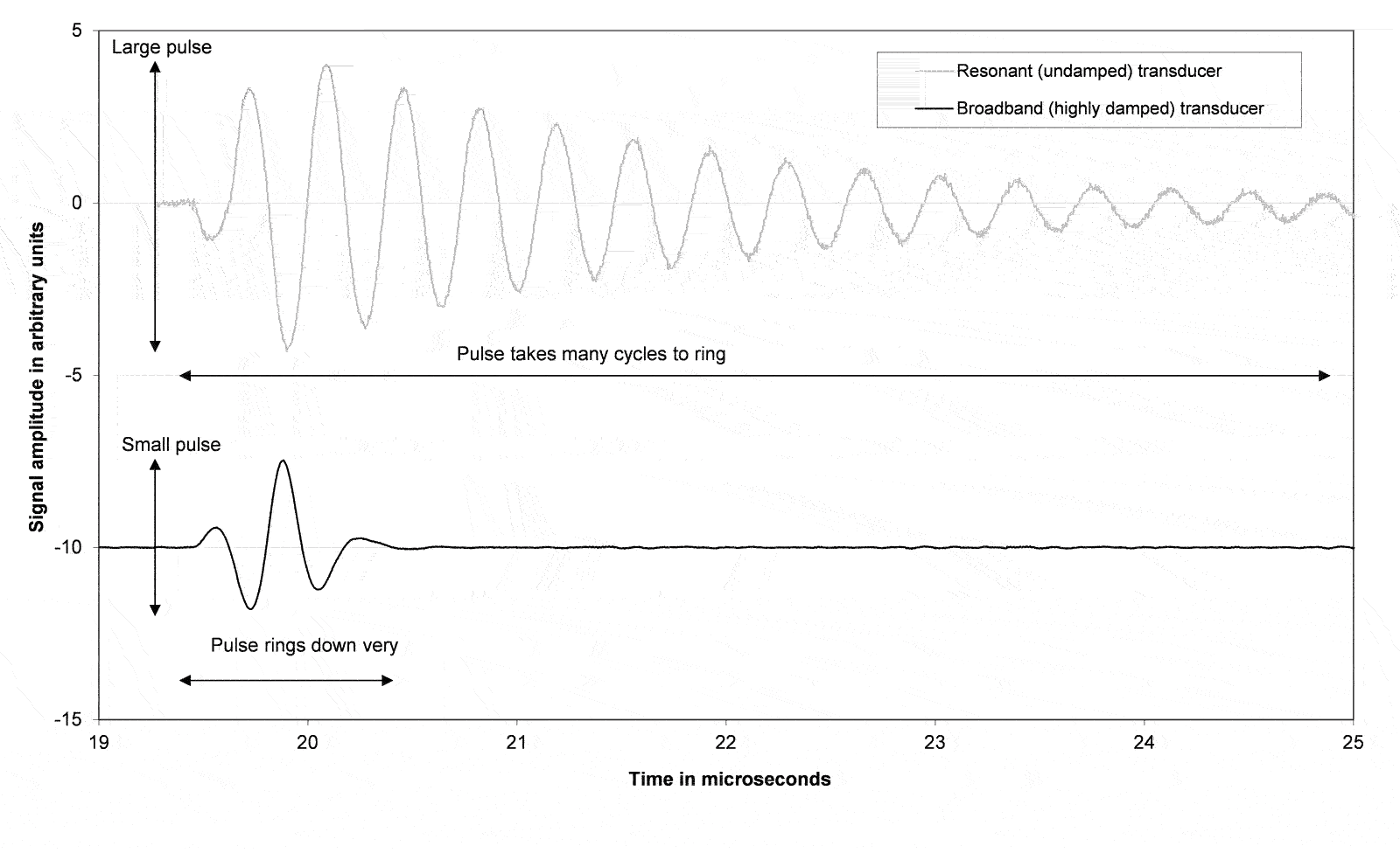
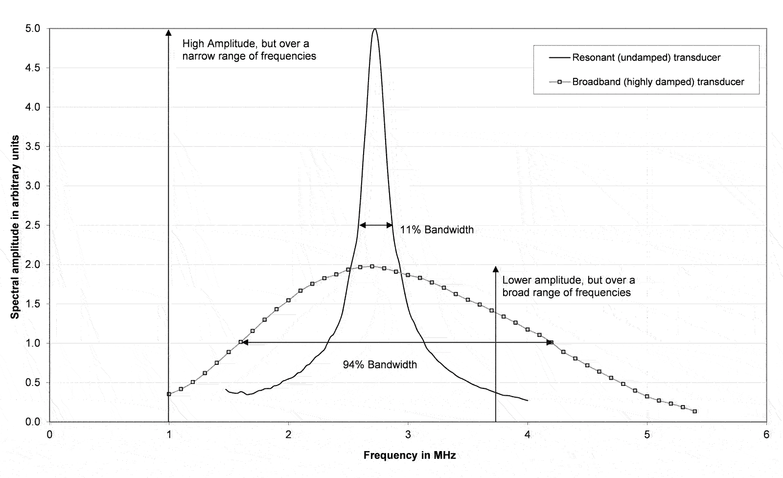
All piezo-electric transducers are resonant devices. The performance of a resonant device is significantly affected by how much damping is applied as can be seen in the graph below. The description that follows will consider the two extreme conditions of very low, and very high damping. However, Precision Acoustics is also able to produce transducers with damping anywhere between these two limits.

An undamped (or resonant) transducer will produce a large output very close to its resonant frequency, but the amplitude of its response will decrease significantly away from the centre frequency. In contrast a highly damped transducer will produce a much lower output, but is capable of driving at a range of frequencies either side of the centre frequency.
It is common practice to describe this behaviour in terms of percentage bandwidth: the ratio of bandwidth and centre frequency. An undamped transducer will have a low percentage bandwidth, but high maximum output at resonance. Conversely a damped transducer will have a high percentage bandwidth, but with a lower maximum output.

It is also important to understand the effect that damping has on the time domain waveform produced by a transducer. A damped transducer will produce less acoustic output than a comparable resonant transducer, but it will have relatively short pulse duration. In contrast, an undamped transducer will produce a much larger output, but because it is a resonant device, the pulse will ring on for many cycles. It is this relationship between damping and resonance that means it is not possible to produce a high power output across a broad range of frequencies.
A summary of properties of the resonant and undamped transducers can be found in the table below:
| Resonant | Damped | |
| Percentage bandwidth | Low | High |
| Amplitude at centre frequency | High | Medium |
| Amplitude away from centre frequency | Low | Medium/Low |
| Time domain impulse response | >8 cycles | 2-3 cycles |
| Common drive signals | Continuous Wave or Toneburst | Swept sine wave (chirps) or pulses |
| Common applications | Physiotherapy, HIFU, ultrasonic heating, ultrasonic cleaning | Pulse/Echo, NDT, diagnostic imaging, Time of Flight measurements |
Piezo-ceramic materials are characterised by having good electrical to mechanical conversion capabilities, but relatively low internal damping. This makes them very good for producing resonant transducers, but they have to be damped heavily to produce broadband transducers. A typical heavily damped piezo-ceramic transducer will probably have a pulse that is 4-5 cycles long. They make excellent transmitting transducers and a reasonable choice for transmit/receive devices
Almost all piezo-ceramic transducers are supplied with an integral quarter wave matching layer to effectively couple the high characteristic acoustic impedance of piezo-ceramics (typically in excess of 30 MRayls) into the 1.5 MRayls load that is presented by water. Most Precision Acoustics piezo-ceramic transducers contain an integral electrical impedance matching network. This transforms the complex impedance presented by the transducer to something much closer to 50 Ω. This ensures optimum power transfer into the transducer from typical 50 Ω output impedance function generators and amplifiers.
Very high frequency devices are difficult to produce with piezo-ceramics because the crystals become very thin and prone to damage. Precision Acoustics normally only produces piezo-ceramic devices with centre frequencies of 10 MHz and lower. Piezo-ceramics have also been used in-house to produce highly resonant transducers with acoustic outputs in excess of 85W.
Piezo-polymer materials (e.g. PVdF) are characterised by having good mechanical to electrical conversion capabilities, but relatively high internal damping. This makes them very good for producing very short pulse, broadband transducers and impulse responses of-2-3 cycles are possible. However, the internal damping means that they have to be driven by much higher voltage levels than comparable piezo-ceramic devices. They make excellent receiving transducers and a reasonable choice for transmit/receive devices (particularly if good axial resolution is required).
The acoustic impedance of PVdF is very much closer to water than piezo-ceramics, and as such acoustic matching layers are not needed for PVdF based transducers. The nature of the electrical impedance presented by a PVdF transducer means that it is difficult to effectively transform it to 50 Ω. Although the impedance could be matched over a limited frequency range, this would compromise the broadband behaviour of this type of device. Therefore, most Precision Acoustics piezo-polymer transducers are supplied with simple inductive matching (to cancel much of the reactance of the transducer), but are not matched to 50 Ω.
PVdF films can be very thin indeed and therefore can be used to produce high frequency transducers. Miniature piezo-polymer transducers (1mm diameter) have been produced at Precision Acoustics with centre frequencies in excess of 35 MHz.
Calibration FAQ's
NPL uncertainties typically are 7-12% depending on the frequency of the calibration. Precision Acoustics uncertainties are higher, as our references are secondary hydrophones which have been calibrated at NPL and we have to include the NPL uncertainties within our results.
In order to calibrate hydrophones Precision Acoustics must have reference hydrophones that are calibrated over the same range. Precision Acoustics has suitable reference hydrophones calibrated at NPL in London which allows us to calibrate over the range 0.3 MHz to 1 MHz in 50 kHz increments, and 1 MHz to 30 MHz in 1 MHz increments. For calibrations outside this range or smaller increments, we can arrange calibrations at PTB, Germany or NPL, London
3D scanning tanks FAQ's
For measurements on diagnostic scanners we recommend an oscilloscope with sufficient bandwidth and high sampling rate. The oscilloscope is an essential part of our system and we have designed our software around the Keysight Technologies (formerly Agilent) range of oscilloscopes. We usually supply an oscilloscope from the DSO-X 3000 series but we have configured the software for most oscilloscopes in this range. There are also other scopes in the LeCroy and Tektronix ranges that are supported. Please contact us if you have an non-Keysight Technologies oscilloscope to confirm whether it is supported. Even if it is not we may be able to write additional software to extend support to your device
Our software was originally designed to measure the acoustic parameters which relate to ultrasound safety. All measurements rely on the measurements being made with a calibrated hydrophone. If your application is not medical we can customise the software to display those parameters which are relevant to your work. Please contact us with your requirements.
Contact us
If you would like more information, please get in touch by phone, email or enquiry form.
Alternatively complete our enquiry form below.
Telephone:
Email:


